Research portfolio · 01—03

Follow the mechanism, then test the story.

These projects span molecular modelling, industrial route assessment and natural carbon sequestration. What connects them is a disciplined movement from question to evidence—and from evidence to an explanation with clear limits.

01

Computational chemistry · Undergraduate thesis · 2024

Tracing excited-state behaviour back to molecular structure.

The question

How do structural differences between CMOM and CMNM alter absorption, emission and excited-state decay?

My first sustained research project began with two closely related coumarin derivatives. Their structures looked similar, but reporting different optical behaviour was not enough; I wanted to understand where the difference came from.

I optimised ground- and excited-state geometries, included solvent effects through a PCM model in DMSO, examined frontier orbitals and transition composition, and calculated radiative and non-radiative decay behaviour. Moving between structure, energy and rate taught me that a useful calculation is not the end of an analysis—it is one piece of a physical explanation.
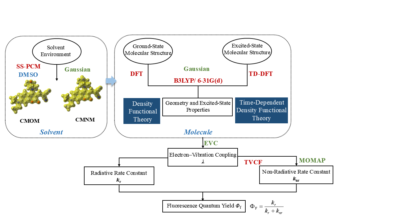

Gaussian 16B3LYP/6-31G(d)PCMTD-DFTMOMAPMultiwfnGaussView
Computational workflow from solvent modelling and molecular-structure calculations to radiative and non-radiative rate constants
Fig 01 Computational workflow linking solvent and molecular models with excited-state properties and fluorescence quantum yield.
Molecular structures of CMOM and CMNM
Fig 02 Molecular structures of CMOM and CMNM.
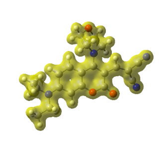
PCM surface model of CMOM
Fig 03A PCM model of CMOM.
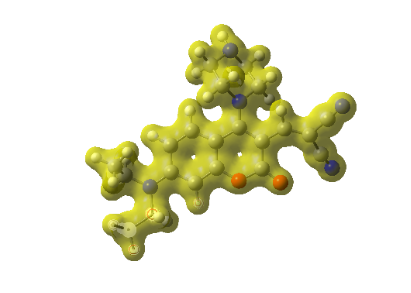
PCM surface model of CMNM
Fig 03B PCM model of CMNM.

From geometry to rate

The explanation emerged by connecting several calculations.

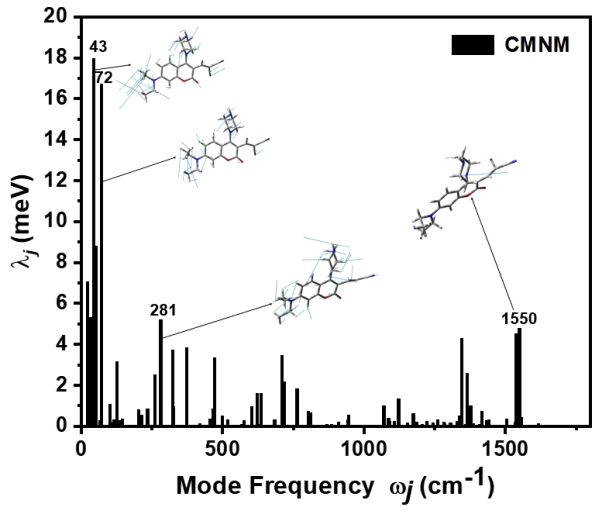
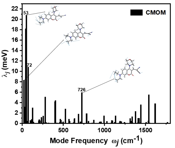
After comparing calculated absorption and emission with available experimental values, I examined where electronic density moved and how each molecule relaxed geometrically. Mode-resolved reorganisation energies then helped identify which motions mattered most.

Key finding: changes in dihedral angles made the largest contribution to reorganisation energy in both molecules, providing a structural route to understanding their non-radiative behaviour.
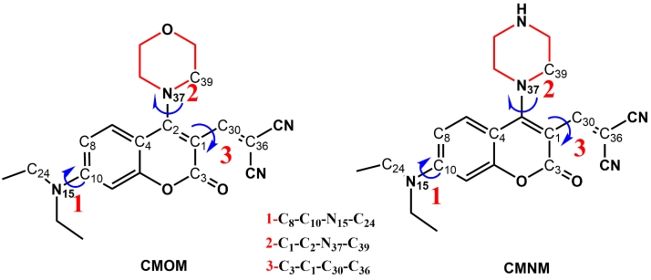
Selected dihedral angles in CMOM and CMNM
Fig 04 Selected dihedral angles used to compare geometric relaxation.
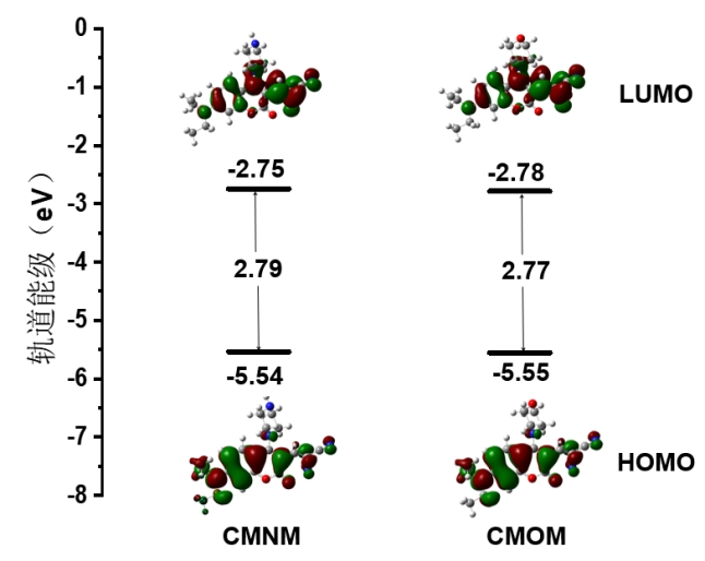
HOMO and LUMO energy levels and electron-density contours of CMNM and CMOM
Fig 05 Frontier-orbital energies and electron-density contours.
Mode-resolved reorganisation energy for CMNM
Fig 06A Mode-resolved reorganisation energy for CMNM.
Mode-resolved reorganisation energy for CMOM
Fig 06B Mode-resolved reorganisation energy for CMOM.
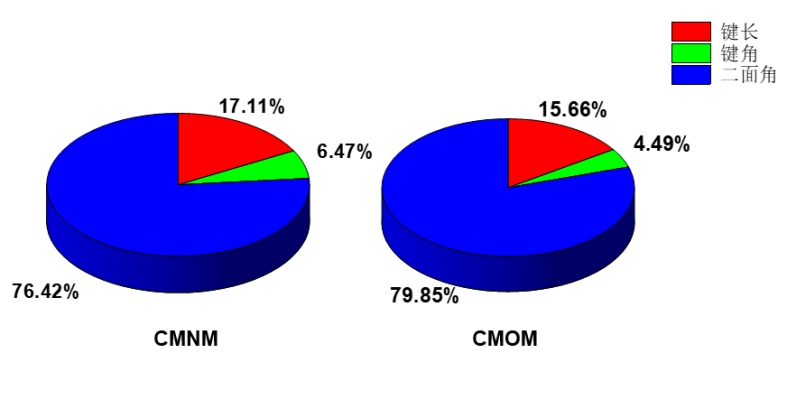
Projection of reorganisation energy onto bond length, bond angle and dihedral changes
Fig 07 Geometric contributions to reorganisation energy.
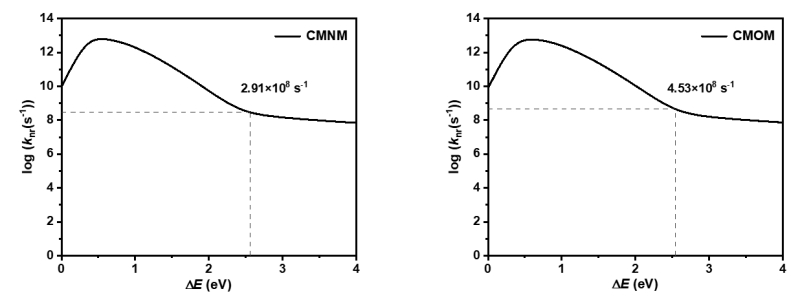
Calculated non-radiative rate profiles for CMNM and CMOM
Fig 08 Calculated non-radiative rate profiles.
What I carried forward

This project gave me a foundation in electronic-structure calculations and, more importantly, a disciplined way to connect molecular structure with measurable behaviour: define the mechanism clearly, test it against evidence and state the limits of the result.
02

Industrial CCUS · Research contributor · 2025–2026

Building a technically credible route under real constraints.

The question

Which hydrate-based capture route remains credible when thermodynamics, mass transfer, promoters and downstream utilisation are considered together?

At master’s level, the scale of the problem changed. A molecule was no longer enough; the proposed route had to survive engineering constraints, collaboration boundaries and an industrial tender.

I reviewed how temperature, pressure, flue-gas composition, mass transfer and promoters influence hydrate formation. I compared enhancement routes and helped develop a concept linking flue-gas capture with fly-ash mineralisation in saline water for a CHN Energy collaboration.

Responsibility boundary: my contribution was literature synthesis, route assessment, process and proposal development, and tender coordination. Hydrate and mineralisation experiments were conducted by a collaborating laboratory.

Technical reviewRoute comparisonProcess conceptScale-up risksTender coordination
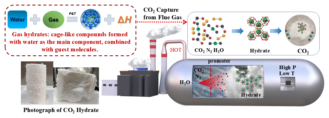
Overview of carbon dioxide capture from flue gas through gas-hydrate formation under high-pressure and low-temperature conditions
Fig 09 CO₂ hydrate capture concept: cage formation and a high-pressure, low-temperature process route.
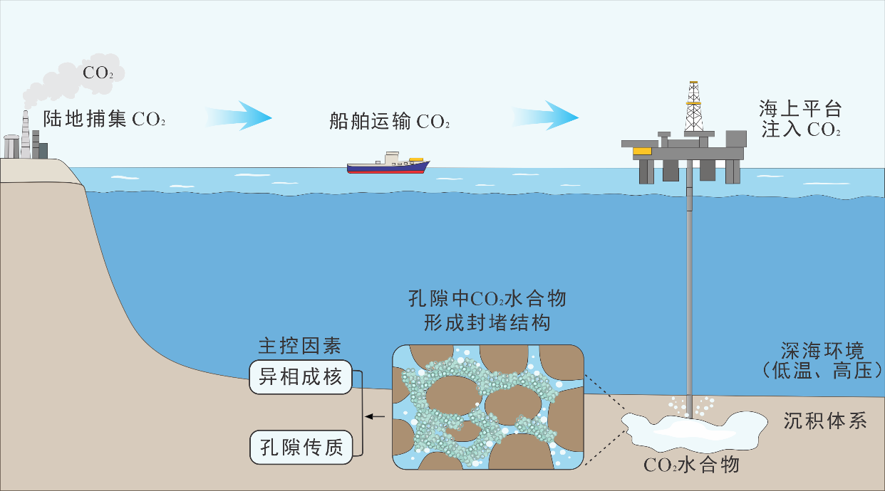
Technical route connecting flue-gas carbon capture with carbon dioxide hydrate storage
Fig 10 Technical route developed during project synthesis: capture, transport and hydrate storage.
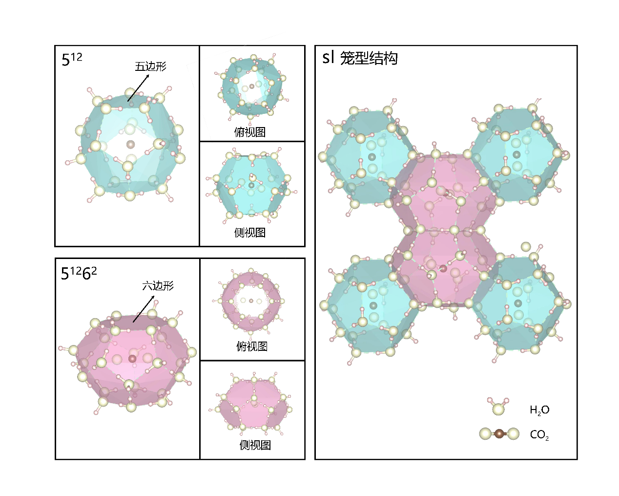
Carbon dioxide hydrate cage structures
Fig 11 CO₂ hydrate cage structures used to explain molecular occupancy.
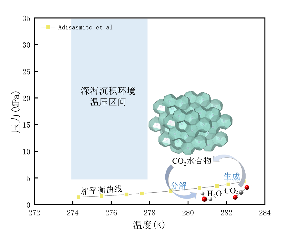
Carbon dioxide hydrate phase-equilibrium curve and deep-sea temperature-pressure window
Fig 12 Phase equilibrium and the deep-sea temperature–pressure window.
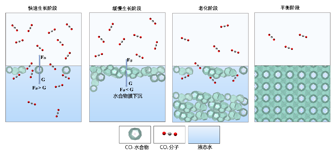
Conceptual stages of carbon dioxide hydrate formation
Fig 13 Conceptual stages of hydrate formation, prepared for technical communication.

Output and communication

Research synthesis became something other people could use.

I helped turn the technical review into a project proposal and a complete tender package. The literature work also developed into a first-author review manuscript on CO₂ hydrate formation mechanisms and promoter effects, now submitted.

The same project became the basis of my oral presentation at the Chemistry & Ocean Future Scientist Forum, where I received First Prize.

What I carried forward

Industrial relevance changes the questions worth asking. A strong mechanism matters, but so do operating windows, material availability, regeneration, integration and evidence strong enough to support a decision.

03

Natural carbon sequestration · Master’s research · current

Learning when a signal supports a mechanism—and when it does not.

The question

What can temperature-resolved CO₂ release and isotope profiles reveal about organic-carbon preservation in Japan Trench sediments?

This project moved me from calculation to hands-on analytical work. I independently prepare sediment samples and operate a ramped pyrolysis/oxidation system coupled to a Picarro cavity ring-down spectrometer.

I process temperature-resolved CO₂ and δ¹³C profiles in Origin, compare event deposits with background sediments, and read those patterns alongside TOC, radiocarbon and elemental evidence. The work has trained me to preserve data provenance, question apparently neat trends and check whether different evidence streams agree.

Sample preparationRPOPicarro CRDSδ¹³CTOCRadiocarbonOrigin
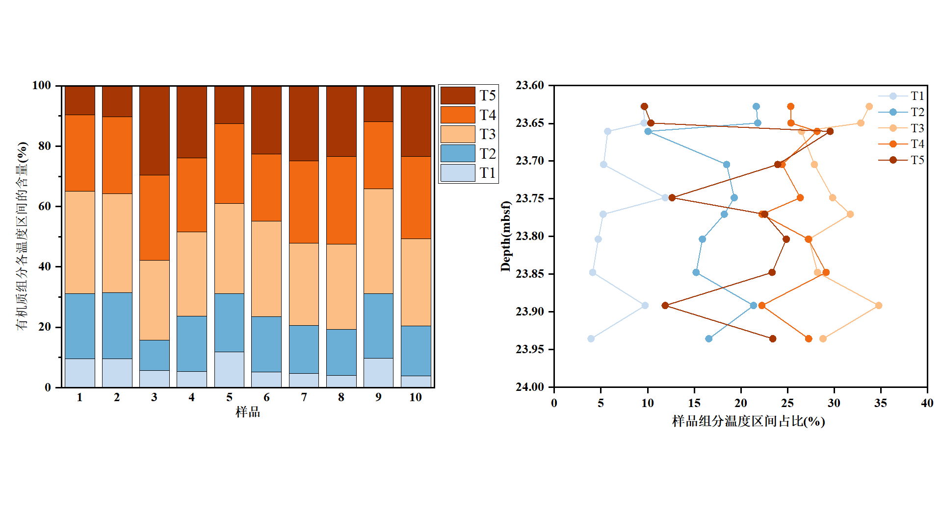
Five-window RPO temperature analysis with carbon dioxide release and isotope profiles
Fig 14 Five-window RPO treatment of temperature-resolved CO₂ release and isotope data.
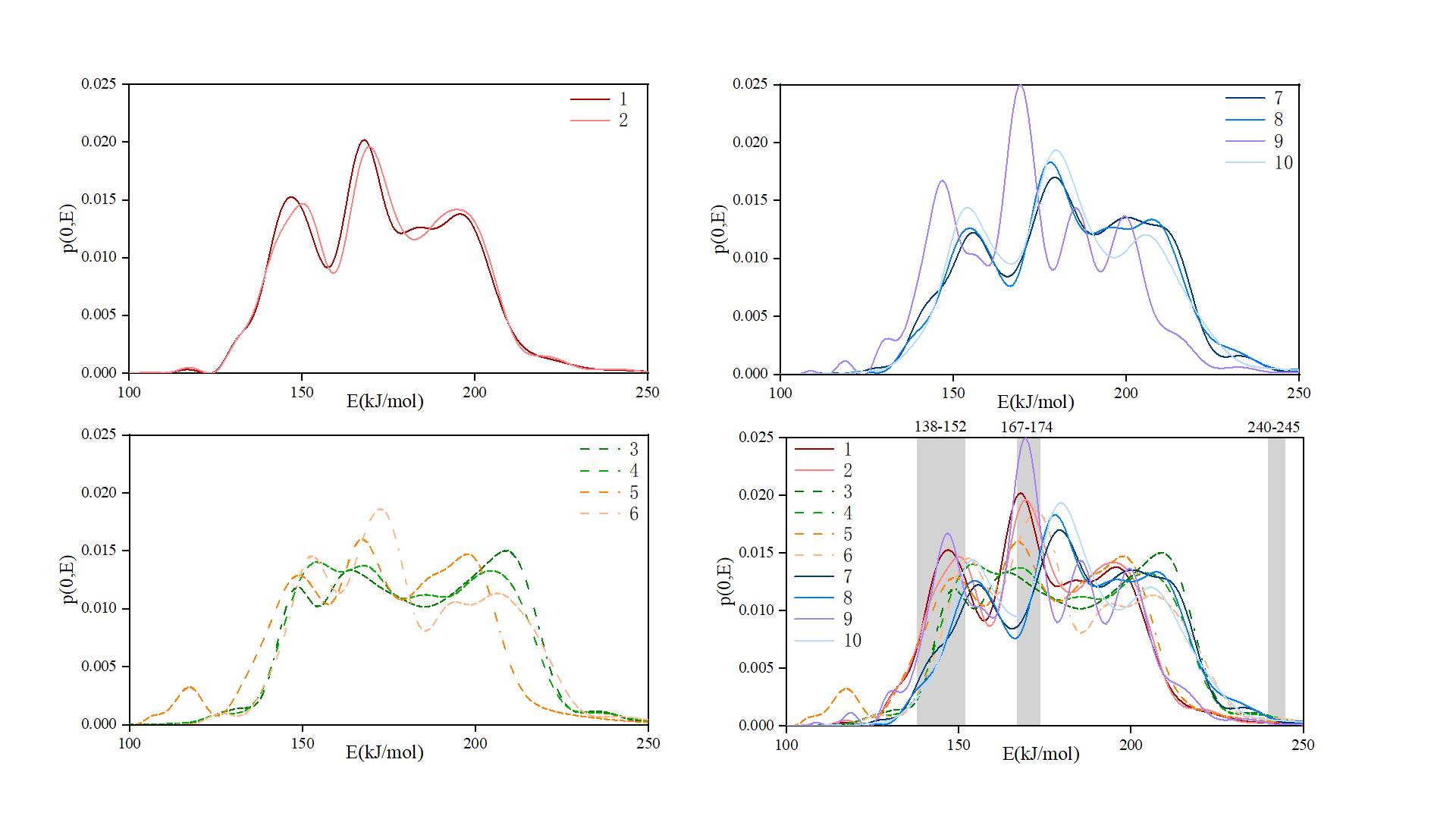
Activation-energy profiles for Japan Trench sediment samples
Fig 15 Activation-energy profiles across sediment samples.
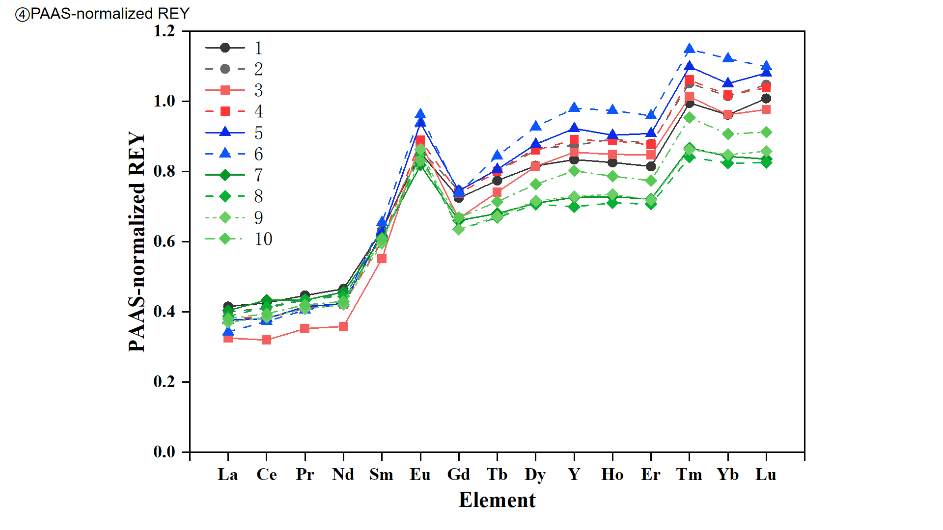
PAAS-normalised rare-earth element profiles
Fig 16 PAAS-normalised REY profiles used as a complementary evidence stream.
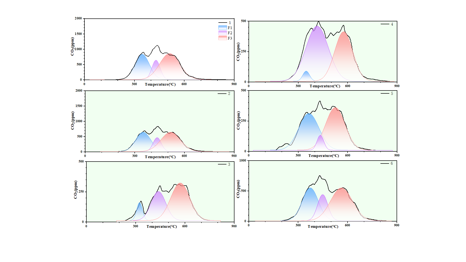
Gaussian peak separation of temperature-resolved sample profiles
Fig 17 Gaussian peak separation used to examine overlapping thermal components.
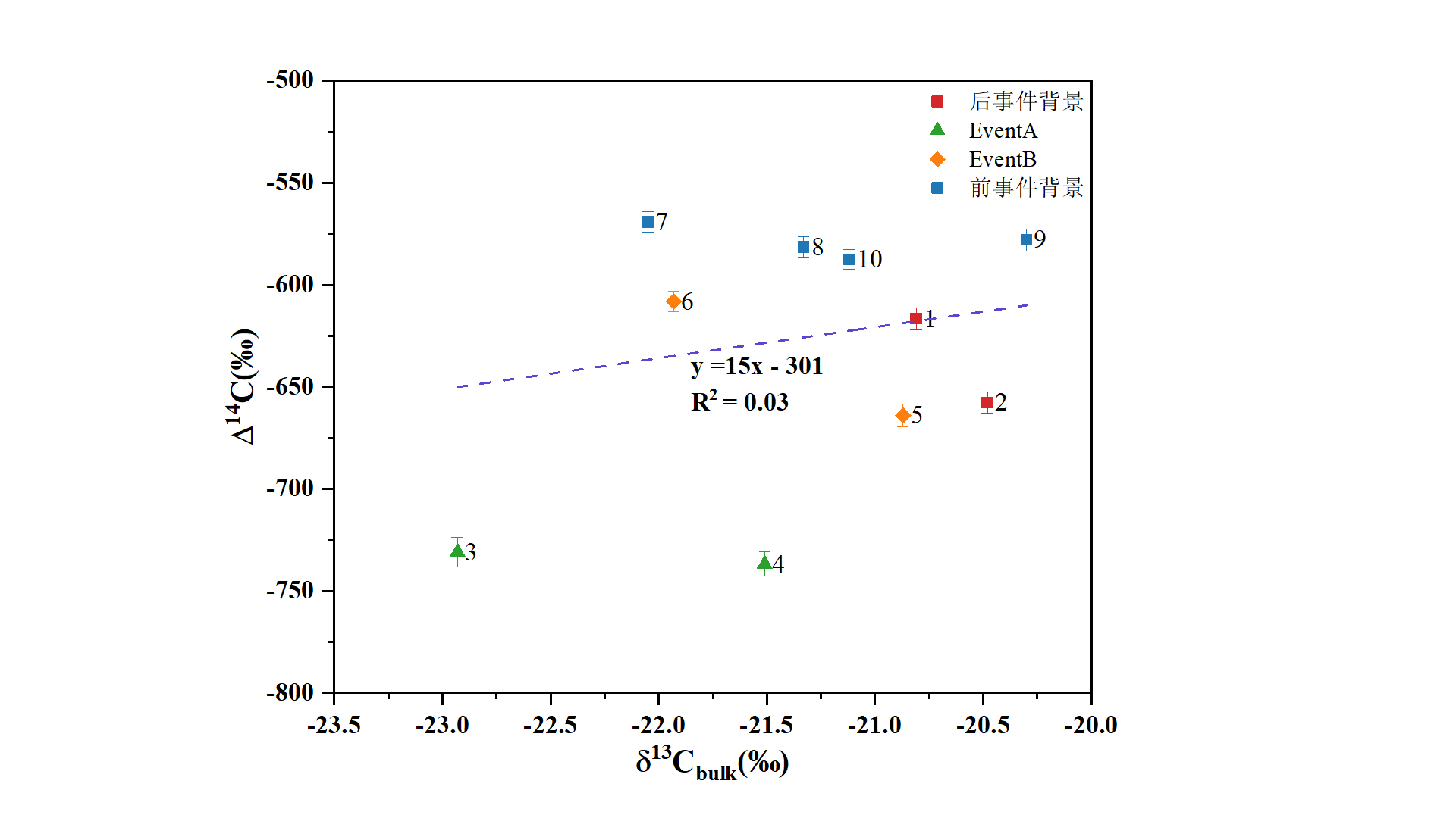
Correlation analysis between isotopic indicators
Fig 18 Indicator correlation analysis and explicit uncertainty.
What I carry forward

The subject is sedimentary carbon, but the transferable skill is broader: independent instrument operation, disciplined signal processing and mechanistic interpretation across multiple measurements. I want to bring that experimental judgement into future work across CCUS.

Research shows what I have done. The journey page shows how I learned to take responsibility when the path was unclear.

Continue to Journey